Our Vision: Support and develop our client’s technical know-how while creating trust
Often, Inspectors and engineers have to make prompt, accurate, and sound decisions concerning the general Mechanical Integrity and Structural Fitness for continued use of in-service systems (piping, Pressure Vessels, Tanks, and peripheral) when indications are found and classified as defect WRT their design standards and operating conditions.
Currently, Plant Reliability engineers, Asset integrity engineers usually have to go through various standards and develop models to compute L1/L2 structural integrity assessments to make Go/No-Go calls during plant runtime and Outage work windows for continued running, repair, replace and required level of follow-up work. Nowadays, plant inspectors are becoming more engaged and needed to make such calls too. This is usually time-consuming, and often, when assessment results are challenged, they are found to have various inconsistencies and assumptions based on the risk profile of the specialist conducting the assessment.
Another approach has been to involve 3rd party consultants with the expectation of advanced knowledge. However, it doesn’t solve the problem of prompt delivery. In addition, it often comes with a high price tag and errors in modeling due to limited 1st hand field knowledge of the defect/system and interpreting customer inspection information while offsite.
The level of assessment, quality of the results, and final decision directly affect the plant’s safety, reliability, productivity, and thus bottom-line. Industrywide (Chemical and Petrochemical), approximately 30% of defects require in-depth and advanced (Level 3) Fitness for Service evaluations which may involve custom modeling and FEA analysis. The other 70% need less rigor; the component design standard and Level 1 or 2 fitness for service evaluation are appropriate and usually sufficient. The focus of Rapidsolve™ is this 70%.
Rapidsolve™ is developed to give prompt, accurate, and consistent L1/L2 defect evaluation and results in minutes.
Rapidsolve™ is Modelled primarily around the API579-1 FFS and many years of recognized and generally accepted good engineering practices REGAGEP. Certified engineers did the code validations and SMEs using actual plant defect findings and case scenarios in API579-1 and API579-2. A good understanding of the concept of FFS as specified in API597-1 is required to use and interpret the results using this application properly.
Rapidsolve™ is not intended to replace provincial/state requirements, Design Standard guidelines, and user-owner risk profile models. It is not a detailed engineering analysis and is not intended to be a comprehensive tool. The tool does not consider advanced level assessment approaches and several complex external loads and conditions. The use of this tool requires adequate knowledge of the steps and limitations as specified in the applicable design standard and FFS-API579-1 standard of the defect analyzed. Engineering analysis plus Level 3 are required when the limits as detailed in the standard relate to a system in question. The software entails the following features and level of assessment capabilities:
- Structural Integrity & fitness procedure for Defects & Damage Mechanisms.
- Prompt & Accurate Analysis. Visual Aids and graphs for defect illustration.
- Simple Go/No Go Step-wise screening for Repair-Rerate-Replace FFS decisions.
- Cloud-based Access. No computer installation is required. Free Updates!
- Assessment procedures Verified with known actual and verifiable cases.
- Review & Updates by SME Engineers and Inspectors using a MOC/SR process.
Brittle Fracture Part 3 (L1 & L2)
Assessment Procedure specified uses Method A and B Only of the reference code API579-1/ASME FFS-1. This explores evaluating the resistance to brittle fracture of existing carbon and low alloy steel pressure vessels, piping, and storage tanks. Criteria are provided to assess normal operating, start-up, upset, and shut-down conditions. Procedure assessment condition exceptions: Systems under substantial supplementary loads, full vacuum conditions, and application when Impact Test Results are unavailable. System Geometry: Cylindrical and Conical profile only.
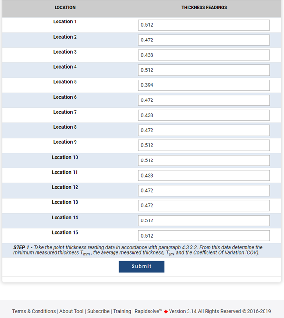
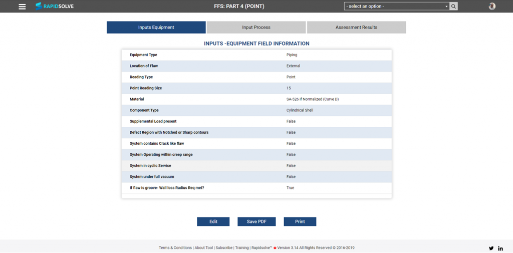
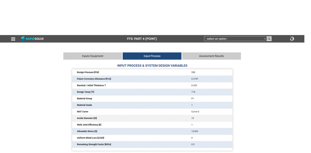
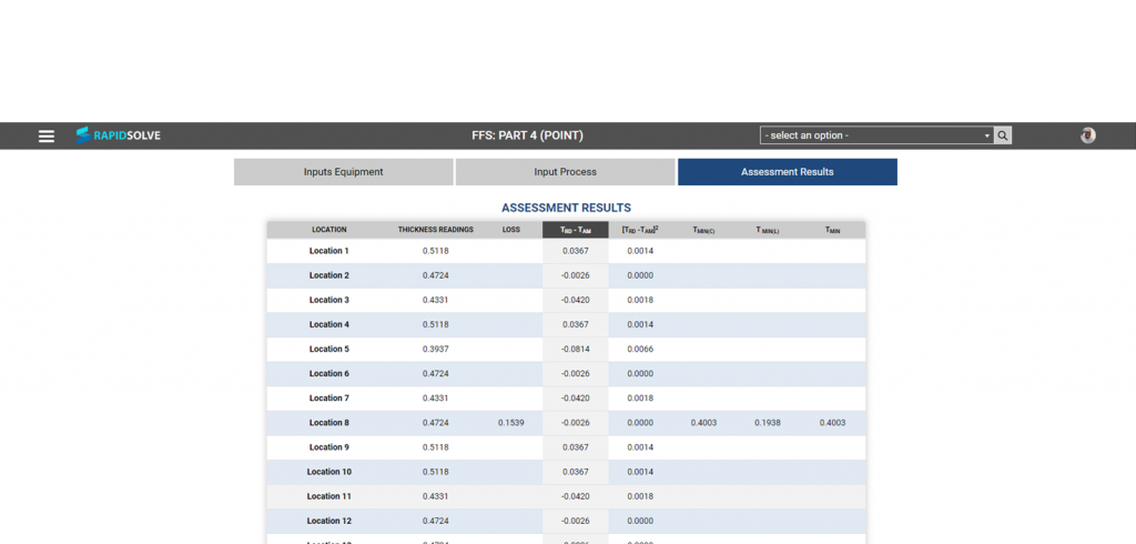
General Metal Loss Part 4 (L1 & L2)
Assessment procedures specified explores cases of general corrosion. Thickness data used for the assessment can be either point thickness readings or Grid detailed thickness profiles. When the Metal loss profile is not general, the method and approach in the assessment procedures of Part 5 are applicable. Procedure assessment condition exceptions: Systems under substantial supplementary loads, full vacuum conditions, and application when Impact Test Results are unavailable. System Geometry: Cylindrical and Conical profile only.
Local Metal Loss Part 5 (L1 & L2)
Assessment procedures specified explores cases of single Thin Ares, closely spaced Local Thin Areas LTSs and groove-like flaws. Thickness data used for the assessment can be either point thickness readings or precise thickness profiles (Grid). In addition, the procedure can be utilized to assess standalone pits or blisters as per Part 6 and Part 7. When the Metal loss profile is not localized, the method and approach in the assessment procedures of Part 4 are applicable. Procedure assessment condition exceptions: Systems under substantial supplementary loads, full vacuum conditions, and application when Impact Test Results are unavailable. System Geometry: Cylindrical and Conical profile only.
Pitting Corrosion Part 6 (L1 & L2)
Assessment procedures specified explores cases to evaluate systems with widely scattered pitting, localized pitting. The procedure is also applicable to assessing closely spaced blisters as provided for in Part 7. Procedure assessment condition exceptions: Pitting, which occurs within a region of local metal loss, and an area of localized metal loss located within a region of widely scattered pitting are not covered. Systems under substantial supplementary loads, full vacuum conditions, and application when Impact Test Results are unavailable. System Geometry: Cylindrical and Conical profile only.
Blisters and HIC/SOHIC Damage Part 7 (L1 & L2)
Assessment procedures specified explores cases to evaluate systems with isolated and closely spaced and multiple blisters and HIC/SOHIC Damage. The assessment is applicable for blisters and HIC/SOHIC damage located around weld joints and near structural discontinuities/transitions on the system/component as appropriate. Procedure assessment condition exceptions: Systems under substantial supplementary loads, full vacuum conditions, and application when Impact Test Results are unavailable. System Geometry: Cylindrical and Conical profile only.
Weld Misalignment and Shell Distortions. Part 8
Assessment Procedure not specified for this class of defects.
Crack-Like Flaws Part 9 (L1)
Basic assessment procedures specified explores cases to evaluate crack-like flaws. Procedure exceptions: The application for systems with stress intensity factors, reference stress, and residual stresses are not included. Systems under substantial supplementary loads, full vacuum conditions, and application when Impact Test Results are unavailable. System Geometry: Cylindrical and Conical profile only.
High-Temperature Operation and Creep Part 10 (L1 & L2)
Assessment procedures specified explore cases to evaluate systems operating within the creep range and the remaining life (Estimated remaining life and number of remaining cycles). Procedure assessment condition exceptions: Systems under substantial supplementary loads, full vacuum conditions, and application when Impact Test Results are unavailable. System Geometry: Cylindrical and Conical profile only.
Fire Damage Part 11
Assessment Procedure not specified for this class of defects.
Dent, Gouge, and Dent Gouge Combinations Part 12 (L1 & L2)
The specified assessment procedures explore cases to evaluate dent, gouge, and dent gouge combinations. Procedure assessment condition exceptions: Systems under substantial supplementary loads, full vacuum conditions, and application when Impact Test Results are unavailable. System Geometry: Cylindrical and Conical profile only.
Laminations Part 13 (L1 &L2)
Assessment procedures specified explores cases to evaluate systems with laminations. The assessment is applicable for laminations located around weld joints and near structural discontinuities/transitions on the system/component as appropriate. Procedure assessment condition exceptions: Systems under substantial supplementary loads, full vacuum conditions, and application when Impact Test Results are unavailable. System Geometry: Cylindrical and Conical profile only.
Fatigue Part 14
Assessment Procedure not specified for this class of defects.
Pricing: RAPIDSOLVE™ is offered on various terms to support clients. For subscriptions, please contact tech@rapidsolve.ca
Similar Products to Rapidsolve®
- Codeware: API 579 / ASME FFS-1 Software. Principle/Concept (API 579/ API 571).
- Becht Engineering: BechtFFS API 579-1/ASME FFS-1. Principle/Concept (API 579 / API 571)
- Equity engineering: DamagePlus™ / API 579 / ASME FFS. Principle/Concept (API 579 / API 571)
Product differentiation
- Rapidsolve targets promptness and accuracy of analysis for the majority of screening level FFS needs (>70% of field defects which fail the fabrication requirements in the design standard), while other current market products target rigorous assessment and modeling, which eventually require a full fledge advanced level assessment L3 or multi-model /risk reviews. This, in turn, reduces the efficiency proposal of these applications and thus makes the task more daunting and inefficient. Therefore, the rationale of the designers of Rapidsolve is that every advanced level FFS requirement requires a custom based model design and the associated mechanical static + dynamic analysis (Solving the systems boundary problem as a PDE /ODE using Finite element analysis or hand computation) as well as imposing the right level of a risk model to ensure all possible field conditions are captured.
- Current applications are not designed for all assets owners but SMEs / consultants. They typically require very complex problem modeling. These models are often subjective and, as per the engineer’s competence, making the models not replicable or inconsistent. The results require expert-level review due to complex level assumptions imposed on the problem model. For example, inspectors or plant reliability engineers without asset integrity and advanced engineering background and knowledge find them challenging to use. Rapidsolve is tailored in the models presented to work for the field inspectors who require summary Go-No-go decisions that are correct and the engineer who is heavy on the theory and requires more advanced analysis.
Advantages
- Multiple components assessment and what-if scenarios.
- Generate raw input variable and results in sheet (PDF), Save as PDF, Edit in real-time.
- Graphical illustrations and stepwise breakdowns of the in-process driving the results.
- Assessment interpretation is intuitive.
- Product Enhancement for typical IDMS. Rapidsolve can be packaged as a module within Integrity applications to enhance the use of the product and higher value to the software user.
- Support and enhance Client Capabilities around understanding and implementing Asset integrity initiatives.
- Contributor: Process Safety, Asset integrity& Plant Reliability.
Business Case: Incorporation into Existing Inspection Data Management Systems IDMS.
Existing IDMS Application. Top 10 Market Players
- Asset Integrity – Oceaneering: ACET®
- AssetWise Asset Reliability®
- ASpenTech: Aspen Mtell®
- General Electric: APM/Predix (Meridium)®
- Lloyd Register: Capstone RBMI®, All-Asset®
- Integrity: Vision Enterprise®
- Aspen Fidelis Reliability®
- Credosoft: Credo®
- VERACITY® Pipeline software
- SAP- Linear Asset Management LAMS
- Mistras: PCMS®
Siemens: UltraPipe®